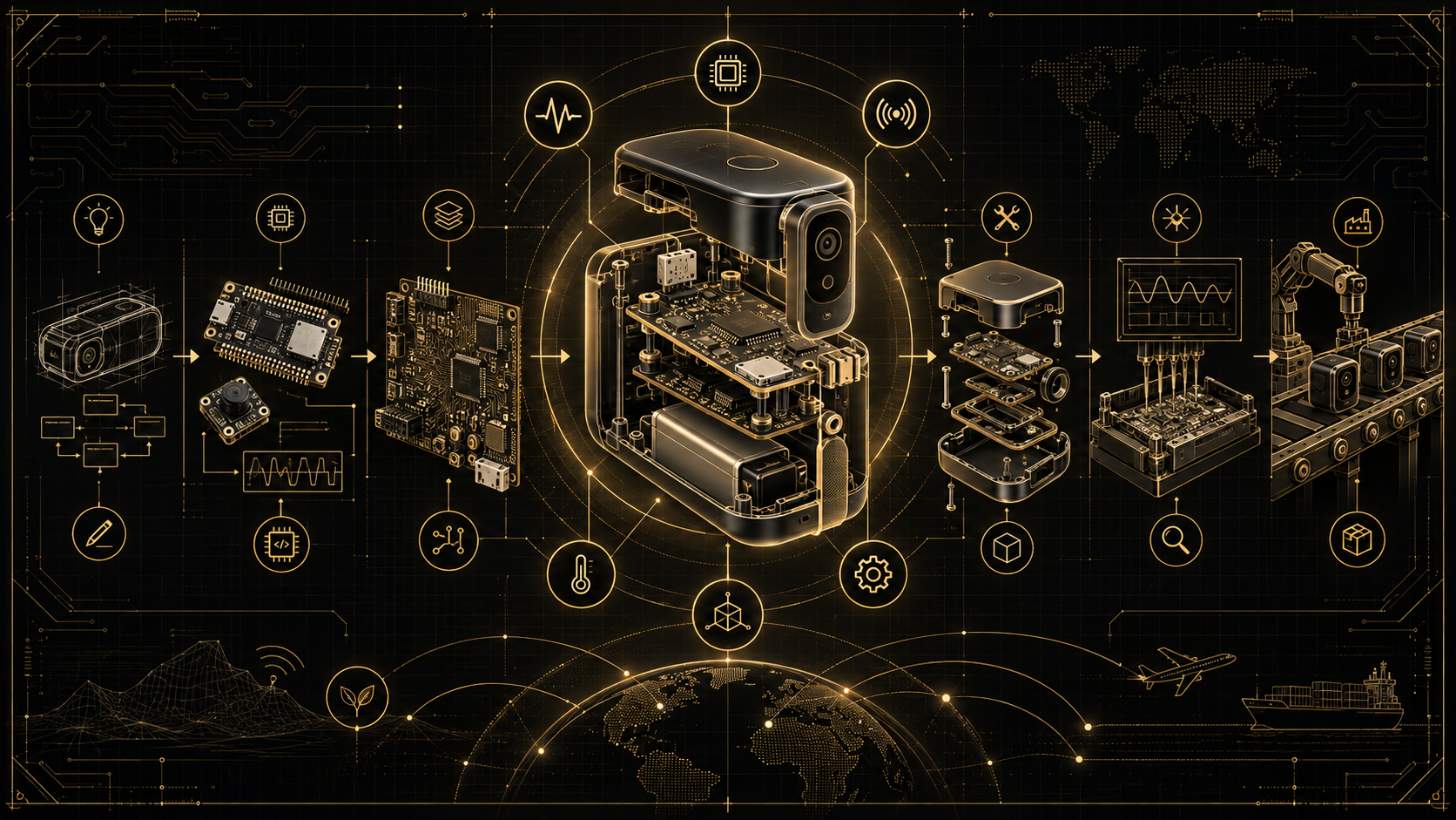
Texas Instruments C2000 microcontrollers are not simply general-purpose MCUs with a few PWM peripherals added around a CPU. They are designed around a different philosophy: deterministic real-time control.
The C2000 architecture combines a fast C28x processing core with peripherals that are tightly coupled to real-time control tasks such as PWM generation, ADC acquisition, protection, mathematical processing and control-loop execution.
For this tutorial we will use the TMS320F280039C as the reference device. It contains a 120 MHz C28x CPU, floating-point hardware, TMU, CLA, CLB, 384 KB Flash, multiple ADCs and a rich set of real-time control peripherals.
The recommended development platform for this tutorial is:
- TMS320F280039C
- LAUNCHXL-F280039C
- Code Composer Studio
- C2000Ware
- C2000 DriverLib
The LAUNCHXL-F280039C board provides an integrated XDS110 debugger and exposes the MCU peripherals for prototyping.
The C28x core and its accelerators
Before going further, it helps to know what is inside the device. The C28x is a 32-bit CPU optimised for control math; on the F280039C it runs at 120 MHz with a hardware FPU (single-precision floating point). Around it sit several accelerators that make real-time control fast:
- TMU (Trigonometric Math Unit): hardware acceleration for sine, cosine, division and square-root — essential for the Park/Clarke transforms used in motor control.
- CLA (Control Law Accelerator): an independent 32-bit floating-point co-processor that can run an entire control loop in parallel with the CPU, keeping the main core free for communications and supervision.
- CLB (Configurable Logic Block): small FPGA-like programmable logic inside the MCU, used to build custom digital functions (special PWM patterns, position decoding, glue logic) without external parts.
The device also includes multiple 12-bit ADCs, on-chip comparators (CMPSS), DACs, and the ePWM / eCAP / eQEP control peripherals. You do not need all of these on day one, but knowing they exist explains why C2000 is chosen for demanding power and motor control.
1. Why C2000 Is Different
A traditional MCU application often follows this pattern:
Read input
↓
Process data
↓
Update output
↓
Repeat
A real-time power-control system is different.
A digital converter may operate at 20 kHz, 50 kHz, 100 kHz or higher. Every switching cycle may require the controller to:
PWM switching event
        ↓
ADC sample at an exact instant
        ↓
ADC conversion complete
        ↓
Control ISR
        ↓
PI/PID/control law
        ↓
New PWM compare value
        ↓
Shadow register update
        ↓
Next switching cycle
Timing is therefore part of the control algorithm.
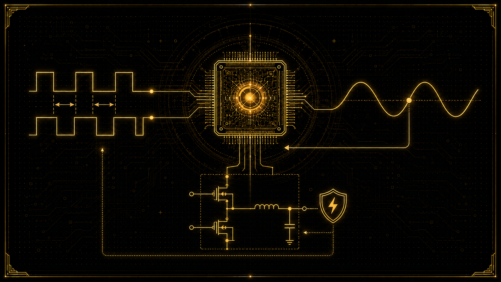
The C2000 ePWM peripheral can directly generate ADC start-of-conversion events, while ADC end-of-conversion events can generate CPU interrupts. This allows the sensing and control loop to be synchronized with the switching waveform rather than depending on software delays.
2. Development Environment
2.1 Code Composer Studio
Code Composer Studio, or CCS, is TI's integrated development environment.
It provides:
- C/C++ compiler
- source editor
- debugger
- memory/register inspection
- breakpoints
- watch expressions
- profiling
- Flash programming
- integration with TI SDKs
TI recommends CCS together with C2000Ware for C2000 development.
3. C2000Ware
C2000Ware contains the low-level software infrastructure for C2000 development:
C2000Ware
│
├── DriverLib
├── device support
├── peripheral examples
├── communication examples
├── control libraries
├── DSP libraries
├── Flash utilities
└── board examples
DriverLib is particularly important.
Instead of manipulating registers manually:
EPwm1Regs.CMPA.bit.CMPA = value;we can use:
EPWM_setCounterCompareValue(
    EPWM1_BASE,
    EPWM_COUNTER_COMPARE_A,
    value
);
DriverLib provides C APIs for almost all C2000 peripherals while still operating close to the hardware.
4. The Minimal C2000 Program
A typical DriverLib application starts like this:
#include "driverlib.h"
#include "device.h"

int main(void)
{
    Device_init();

    Device_initGPIO();

    Interrupt_initModule();
    Interrupt_initVectorTable();

    EINT;
    ERTM;

    while(1)
    {
    }
}
Device_init() normally performs basic device initialization including clock and watchdog configuration according to the device-support implementation.
Device_initGPIO() prepares GPIO control.
The interrupt controller is then initialized before interrupts are enabled.
This will become the basic structure of all the projects in this tutorial.
5. Understanding ePWM
The enhanced PWM peripheral is one of the most important parts of a C2000 MCU.
Internally an ePWM module contains several important blocks:
Time Base
    ↓
Counter Compare
    ↓
Action Qualifier
    ↓
Dead Band
    ↓
Trip Zone
    ↓
PWM Output
The Time Base defines the switching period.
The Counter Compare registers define important timing points.
The Action Qualifier determines what happens to the output when those timing points are reached.
For example:
Counter = ZERO     → PWM HIGH

Counter = CMPA     → PWM LOW
TI DriverLib exposes APIs including EPWM_setTimeBasePeriod() and EPWM_setCounterCompareValue() for this configuration.
6. Up-Count Versus Up-Down Count
Two commonly used PWM modes are:
Up Count

0 → PERIOD → 0 → PERIOD
and:
Up-Down Count

0 → PERIOD → 0 → PERIOD → 0
Up-down mode creates naturally center-aligned PWM and is frequently useful in power converters and motor-control systems.
For an up-down counter:
PWM frequency =
TBCLK / (2 × TBPRD)
If the timer clock is 120 MHz and we want 20 kHz:
TBPRD =
120,000,000 / (2 × 20,000)

TBPRD = 3000
PROJECT 1 — Precision Center-Aligned PWM
We will generate:
PWM frequency = 20 kHz
Duty cycle    = 50 %
Mode          = center aligned
Output        = EPWM1A
The following example uses GPIO0 as EPWM1A.
#include "driverlib.h"
#include "device.h"

#define PWM_FREQUENCY_HZ   20000UL
#define INITIAL_DUTY       0.50f

static uint16_t pwmPeriod;

void initEPWM1(void);
void setPWMDuty(float duty);

int main(void)
{
    Device_init();
    Device_initGPIO();

    Interrupt_initModule();
    Interrupt_initVectorTable();

    GPIO_setPinConfig(GPIO_0_EPWM1_A);

    SysCtl_disablePeripheral(SYSCTL_PERIPH_CLK_TBCLKSYNC);

    initEPWM1();

    SysCtl_enablePeripheral(SYSCTL_PERIPH_CLK_TBCLKSYNC);

    EINT;
    ERTM;

    setPWMDuty(INITIAL_DUTY);

    while(1)
    {
    }
}

void initEPWM1(void)
{
    pwmPeriod =
        (uint16_t)(
            DEVICE_SYSCLK_FREQ /
            (2UL * PWM_FREQUENCY_HZ)
        );

    EPWM_setClockPrescaler(
        EPWM1_BASE,
        EPWM_CLOCK_DIVIDER_1,
        EPWM_HSCLOCK_DIVIDER_1
    );

    EPWM_setTimeBaseCounterMode(
        EPWM1_BASE,
        EPWM_COUNTER_MODE_UP_DOWN
    );

    EPWM_setTimeBasePeriod(
        EPWM1_BASE,
        pwmPeriod
    );

    EPWM_setTimeBaseCounter(
        EPWM1_BASE,
        0U
    );

    EPWM_setCounterCompareShadowLoadMode(
        EPWM1_BASE,
        EPWM_COUNTER_COMPARE_A,
        EPWM_COMP_LOAD_ON_CNTR_ZERO
    );

    EPWM_setActionQualifierAction(
        EPWM1_BASE,
        EPWM_AQ_OUTPUT_A,
        EPWM_AQ_OUTPUT_HIGH,
        EPWM_AQ_OUTPUT_ON_TIMEBASE_ZERO
    );

    EPWM_setActionQualifierAction(
        EPWM1_BASE,
        EPWM_AQ_OUTPUT_A,
        EPWM_AQ_OUTPUT_LOW,
        EPWM_AQ_OUTPUT_ON_TIMEBASE_UP_CMPA
    );

    EPWM_setActionQualifierAction(
        EPWM1_BASE,
        EPWM_AQ_OUTPUT_A,
        EPWM_AQ_OUTPUT_HIGH,
        EPWM_AQ_OUTPUT_ON_TIMEBASE_DOWN_CMPA
    );

    setPWMDuty(INITIAL_DUTY);
}

void setPWMDuty(float duty)
{
    uint16_t compare;

    if(duty < 0.0f)
        duty = 0.0f;

    if(duty > 1.0f)
        duty = 1.0f;

    compare =
        (uint16_t)(
            duty * (float)pwmPeriod
        );

    EPWM_setCounterCompareValue(
        EPWM1_BASE,
        EPWM_COUNTER_COMPARE_A,
        compare
    );
}
The Action Qualifier can change PWM state on events such as counter zero, period, up-count compare and down-count compare.
Because CMPA uses a shadow-load mechanism, a new duty cycle can be prepared by software and transferred to the active timing hardware at a deterministic timer event.
That is extremely important in real-time control.
7. Complementary PWM
Power converters frequently require two gate-drive signals:
PWM A
PWM B
They must not switch simultaneously.
Otherwise a half bridge may enter shoot-through:
High-side MOSFET ON
+
Low-side MOSFET ON
=
Very large current
The solution is dead time.
PROJECT 2 — Complementary PWM with Dead Time
Suppose we want:
Switching frequency = 20 kHz
Dead time           = 200 ns
PWM A               = high-side
PWM B               = low-side
#include "driverlib.h"
#include "device.h"
#define PWM_FREQUENCY_HZ 20000UL
#define DEADTIME_NS 200UL
static uint16_t pwmPeriod;
static uint16_t deadBandCount;
void initPowerPWM(void);
void setDuty(float duty);
int main(void)
{
Device_init();
Device_initGPIO();
Interrupt_initModule();
Interrupt_initVectorTable();
GPIO_setPinConfig(GPIO_0_EPWM1_A);
GPIO_setPinConfig(GPIO_1_EPWM1_B);
SysCtl_disablePeripheral(
SYSCTL_PERIPH_CLK_TBCLKSYNC
);
initPowerPWM();
SysCtl_enablePeripheral(
SYSCTL_PERIPH_CLK_TBCLKSYNC
);
EINT;
ERTM;
setDuty(0.50f);
while(1)
{
}
}
void initPowerPWM(void)
{
pwmPeriod =
(uint16_t)(
DEVICE_SYSCLK_FREQ /
(2UL * PWM_FREQUENCY_HZ)
);
deadBandCount =
(uint16_t)(
((uint64_t)DEVICE_SYSCLK_FREQ *
DEADTIME_NS) /
1000000000ULL
);
EPWM_setClockPrescaler(
EPWM1_BASE,
EPWM_CLOCK_DIVIDER_1,
EPWM_HSCLOCK_DIVIDER_1
);
EPWM_setTimeBaseCounterMode(
EPWM1_BASE,
EPWM_COUNTER_MODE_UP_DOWN
);
EPWM_setTimeBasePeriod(
EPWM1_BASE,
pwmPeriod
);
EPWM_setCounterCompareShadowLoadMode(
EPWM1_BASE,
EPWM_COUNTER_COMPARE_A,
EPWM_COMP_LOAD_ON_CNTR_ZERO
);
EPWM_setActionQualifierAction(
EPWM1_BASE,
EPWM_AQ_OUTPUT_A,
EPWM_AQ_OUTPUT_HIGH,
EPWM_AQ_OUTPUT_ON_TIMEBASE_ZERO
);
EPWM_setActionQualifierAction(
EPWM1_BASE,
EPWM_AQ_OUTPUT_A,
EPWM_AQ_OUTPUT_LOW,
EPWM_AQ_OUTPUT_ON_TIMEBASE_UP_CMPA
);
EPWM_setActionQualifierAction(
EPWM1_BASE,
EPWM_AQ_OUTPUT_A,
EPWM_AQ_OUTPUT_HIGH,
EPWM_AQ_OUTPUT_ON_TIMEBASE_DOWN_CMPA
);
EPWM_setRisingEdgeDeadBandDelayInput(
EPWM1_BASE,
EPWM_DB_INPUT_EPWMA
);
EPWM_setFallingEdgeDeadBandDelayInput(
EPWM1_BASE,
EPWM_DB_INPUT_EPWMA
);
EPWM_setDeadBandDelayMode(
EPWM1_BASE,
EPWM_DB_RED,
true
);
EPWM_setDeadBandDelayMode(
EPWM1_BASE,
EPWM_DB_FED,
true
);
EPWM_setDeadBandDelayPolarity(
EPWM1_BASE,
EPWM_DB_RED,
EPWM_DB_POLARITY_ACTIVE_HIGH
);
EPWM_setDeadBandDelayPolarity(
EPWM1_BASE,
EPWM_DB_FED,
EPWM_DB_POLARITY_ACTIVE_LOW
);
EPWM_setRisingEdgeDelayCount(
EPWM1_BASE,
deadBandCount
);
EPWM_setFallingEdgeDelayCount(
EPWM1_BASE,
deadBandCount
);
setDuty(0.50f);
}
void setDuty(float duty)
{
if(duty < 0.05f)
duty = 0.05f;
if(duty > 0.95f)
duty = 0.95f;
EPWM_setCounterCompareValue(
EPWM1_BASE,
EPWM_COUNTER_COMPARE_A,
(uint16_t)(
duty * (float)pwmPeriod
)
);
}The ePWM dead-band module supports independent rising-edge and falling-edge delay configuration through DriverLib.
The 5–95% duty limitation used here is an application-level safety constraint rather than an MCU limitation.
8. Why Software-Triggered ADC Sampling Is Usually Wrong
Consider a switching converter.
If software simply executes:
readADC();whenever the main loop happens to reach that instruction, the sample position moves relative to the PWM waveform.
You may occasionally sample:
clean currentand another time sample:
switching transientThat introduces measurement noise and timing uncertainty.
A better architecture is:
ePWM event
    ↓
ADC SOC
    ↓
ADC conversion
    ↓
ADC interrupt
    ↓
control algorithm
The C2000 ADC supports SOC configuration and ePWM can directly generate SOCA/SOCB triggers.
Triggering the SOC at the counter zero (or period) event of a center-aligned up-down PWM samples at the symmetric mid-point of the switching interval — the moment when ripple is cleanest and switching transients have already settled. That is exactly why this ePWM-to-ADC pattern is standard practice in digital power, and why the sample position is treated as part of the control design rather than an afterthought.
PROJECT 3 — PWM-Synchronized ADC Measurement
We will now sample ADCINA0 at exactly the same position during every PWM cycle.
#include "driverlib.h"
#include "device.h"

#define PWM_FREQUENCY_HZ   20000UL

volatile uint16_t adcRaw = 0U;
volatile float adcVoltage = 0.0f;

static uint16_t pwmPeriod;

void initPWM(void);
void initADC(void);
__interrupt void adcA1ISR(void);

int main(void)
{
    Device_init();
    Device_initGPIO();

    Interrupt_initModule();
    Interrupt_initVectorTable();

    GPIO_setPinConfig(GPIO_0_EPWM1_A);

    Interrupt_register(
        INT_ADCA1,
        &adcA1ISR
    );

    SysCtl_disablePeripheral(
        SYSCTL_PERIPH_CLK_TBCLKSYNC
    );

    initPWM();
    initADC();

    SysCtl_enablePeripheral(
        SYSCTL_PERIPH_CLK_TBCLKSYNC
    );

    Interrupt_enable(INT_ADCA1);

    EINT;
    ERTM;

    while(1)
    {
    }
}

void initPWM(void)
{
    pwmPeriod =
        (uint16_t)(
            DEVICE_SYSCLK_FREQ /
            (2UL * PWM_FREQUENCY_HZ)
        );

    EPWM_setClockPrescaler(
        EPWM1_BASE,
        EPWM_CLOCK_DIVIDER_1,
        EPWM_HSCLOCK_DIVIDER_1
    );

    EPWM_setTimeBaseCounterMode(
        EPWM1_BASE,
        EPWM_COUNTER_MODE_UP_DOWN
    );

    EPWM_setTimeBasePeriod(
        EPWM1_BASE,
        pwmPeriod
    );

    EPWM_setCounterCompareValue(
        EPWM1_BASE,
        EPWM_COUNTER_COMPARE_A,
        pwmPeriod / 2U
    );

    EPWM_setActionQualifierAction(
        EPWM1_BASE,
        EPWM_AQ_OUTPUT_A,
        EPWM_AQ_OUTPUT_HIGH,
        EPWM_AQ_OUTPUT_ON_TIMEBASE_ZERO
    );

    EPWM_setActionQualifierAction(
        EPWM1_BASE,
        EPWM_AQ_OUTPUT_A,
        EPWM_AQ_OUTPUT_LOW,
        EPWM_AQ_OUTPUT_ON_TIMEBASE_UP_CMPA
    );

    EPWM_setActionQualifierAction(
        EPWM1_BASE,
        EPWM_AQ_OUTPUT_A,
        EPWM_AQ_OUTPUT_HIGH,
        EPWM_AQ_OUTPUT_ON_TIMEBASE_DOWN_CMPA
    );

    EPWM_setADCTriggerSource(
        EPWM1_BASE,
        EPWM_SOC_A,
        EPWM_SOC_TBCTR_ZERO
    );

    EPWM_setADCTriggerEventPrescale(
        EPWM1_BASE,
        EPWM_SOC_A,
        1U
    );

    EPWM_enableADCTrigger(
        EPWM1_BASE,
        EPWM_SOC_A
    );
}

void initADC(void)
{
    ADC_setVREF(
        ADCA_BASE,
        ADC_REFERENCE_INTERNAL,
        ADC_REFERENCE_3_3V
    );

    ADC_setPrescaler(
        ADCA_BASE,
        ADC_CLK_DIV_4_0
    );

    ADC_setInterruptPulseMode(
        ADCA_BASE,
        ADC_PULSE_END_OF_CONV
    );

    ADC_enableConverter(ADCA_BASE);

    DEVICE_DELAY_US(1000);

    ADC_setupSOC(
        ADCA_BASE,
        ADC_SOC_NUMBER0,
        ADC_TRIGGER_EPWM1_SOCA,
        ADC_CH_ADCIN0,
        20U
    );

    ADC_setInterruptSource(
        ADCA_BASE,
        ADC_INT_NUMBER1,
        ADC_SOC_NUMBER0
    );

    ADC_clearInterruptStatus(
        ADCA_BASE,
        ADC_INT_NUMBER1
    );

    ADC_enableInterrupt(
        ADCA_BASE,
        ADC_INT_NUMBER1
    );
}

__interrupt void adcA1ISR(void)
{
    adcRaw =
        ADC_readResult(
            ADCARESULT_BASE,
            ADC_SOC_NUMBER0
        );

    adcVoltage =
        ((float)adcRaw * 3.3f) /
        4095.0f;

    ADC_clearInterruptStatus(
        ADCA_BASE,
        ADC_INT_NUMBER1
    );

    Interrupt_clearACKGroup(
        INTERRUPT_ACK_GROUP1
    );
}
The ADC DriverLib supports configurable prescaling, SOC configuration, interrupt generation and direct reading of individual SOC results. TI specifies that after enabling the ADC converter, sufficient power-up time must be allowed before sampling.
The F28003x DriverLib also provides internal 2.5 V and 3.3 V reference configuration through ADC_setVREF().
ADC Post-Processing Blocks (PPB)
Each C2000 ADC includes Post-Processing Blocks — small hardware units that process a conversion result the instant it is ready, before software even runs. A PPB can automatically apply an offset correction, compute the error against a set-point, and perform limit checking (a high/low trip). Crucially, a PPB limit event can be routed to the ePWM Trip Zone, so an out-of-range measurement can shut the power stage down in hardware, with no CPU involvement. PPBs offload routine work from the control ISR and add a fast protection layer.
9. From Measurement to Control
We now have everything required for a real controller:
PWM
↓
ADC trigger
↓
Voltage measurement
↓
Interrupt
↓
Control algorithm
↓
New PWM duty
The next step is closed-loop power conversion.
10. Basic Closed-Loop Control
Suppose we have a DC-DC converter.
The objective is:
Target output voltage = 12.0 VThe measured value is:
VoutThe error becomes:
error = Vreference - VoutA proportional-integral controller is:
u = Kp × error + integral

integral =
integral + Ki × error × Ts
where:
Ts = control-loop periodIf the loop executes once per 20 kHz PWM period:
Ts = 1 / 20000

Ts = 50 µs
The resulting controller output can directly determine PWM duty.
PROJECT 4 — Real-Time Closed-Loop Digital Power Controller
This example demonstrates the complete structure of a voltage-mode digital power controller.
The hardware assumptions are:
ADCINA0 = scaled output voltage

0–3.3 V ADC input
corresponds to
0–20 V converter output
The converter itself, gate drivers, voltage divider, isolation and protection hardware are external.
#include "driverlib.h"
#include "device.h"

#define PWM_FREQUENCY_HZ      20000UL

#define ADC_REFERENCE_V       3.3f
#define ADC_MAX_COUNT         4095.0f

#define OUTPUT_SCALE          (20.0f / 3.3f)

#define VOUT_REFERENCE        12.0f

#define KP                    0.040f
#define KI                    20.0f

#define DUTY_MIN              0.05f
#define DUTY_MAX              0.90f

#define CONTROL_TS            \
        (1.0f / (float)PWM_FREQUENCY_HZ)

volatile uint16_t adcRaw = 0U;

volatile float vout = 0.0f;
volatile float error = 0.0f;

volatile float duty = 0.10f;
volatile float integral = 0.0f;

static uint16_t pwmPeriod;

void initPWM(void);
void initADC(void);

void updateDuty(float newDuty);

__interrupt void adcA1ISR(void);

static float clamp(
    float value,
    float minimum,
    float maximum
);

int main(void)
{
    Device_init();
    Device_initGPIO();

    Interrupt_initModule();
    Interrupt_initVectorTable();

    GPIO_setPinConfig(
        GPIO_0_EPWM1_A
    );

    Interrupt_register(
        INT_ADCA1,
        &adcA1ISR
    );

    SysCtl_disablePeripheral(
        SYSCTL_PERIPH_CLK_TBCLKSYNC
    );

    initPWM();
    initADC();

    SysCtl_enablePeripheral(
        SYSCTL_PERIPH_CLK_TBCLKSYNC
    );

    Interrupt_enable(
        INT_ADCA1
    );

    EINT;
    ERTM;

    while(1)
    {
        //
        // Background tasks only.
        //
        // Communication
        // diagnostics
        // telemetry
        // user interface
        //
        // The control algorithm does NOT run here.
        //
    }
}

void initPWM(void)
{
    pwmPeriod =
        (uint16_t)(
            DEVICE_SYSCLK_FREQ /
            (2UL * PWM_FREQUENCY_HZ)
        );

    EPWM_setClockPrescaler(
        EPWM1_BASE,
        EPWM_CLOCK_DIVIDER_1,
        EPWM_HSCLOCK_DIVIDER_1
    );

    EPWM_setTimeBaseCounterMode(
        EPWM1_BASE,
        EPWM_COUNTER_MODE_UP_DOWN
    );

    EPWM_setTimeBasePeriod(
        EPWM1_BASE,
        pwmPeriod
    );

    EPWM_setTimeBaseCounter(
        EPWM1_BASE,
        0U
    );

    EPWM_setCounterCompareShadowLoadMode(
        EPWM1_BASE,
        EPWM_COUNTER_COMPARE_A,
        EPWM_COMP_LOAD_ON_CNTR_ZERO
    );

    EPWM_setActionQualifierAction(
        EPWM1_BASE,
        EPWM_AQ_OUTPUT_A,
        EPWM_AQ_OUTPUT_HIGH,
        EPWM_AQ_OUTPUT_ON_TIMEBASE_ZERO
    );

    EPWM_setActionQualifierAction(
        EPWM1_BASE,
        EPWM_AQ_OUTPUT_A,
        EPWM_AQ_OUTPUT_LOW,
        EPWM_AQ_OUTPUT_ON_TIMEBASE_UP_CMPA
    );

    EPWM_setActionQualifierAction(
        EPWM1_BASE,
        EPWM_AQ_OUTPUT_A,
        EPWM_AQ_OUTPUT_HIGH,
        EPWM_AQ_OUTPUT_ON_TIMEBASE_DOWN_CMPA
    );

    EPWM_setADCTriggerSource(
        EPWM1_BASE,
        EPWM_SOC_A,
        EPWM_SOC_TBCTR_ZERO
    );

    EPWM_setADCTriggerEventPrescale(
        EPWM1_BASE,
        EPWM_SOC_A,
        1U
    );

    EPWM_enableADCTrigger(
        EPWM1_BASE,
        EPWM_SOC_A
    );

    updateDuty(duty);
}

void initADC(void)
{
    ADC_setVREF(
        ADCA_BASE,
        ADC_REFERENCE_INTERNAL,
        ADC_REFERENCE_3_3V
    );

    ADC_setPrescaler(
        ADCA_BASE,
        ADC_CLK_DIV_4_0
    );

    ADC_setInterruptPulseMode(
        ADCA_BASE,
        ADC_PULSE_END_OF_CONV
    );

    ADC_enableConverter(
        ADCA_BASE
    );

    DEVICE_DELAY_US(1000);

    ADC_setupSOC(
        ADCA_BASE,
        ADC_SOC_NUMBER0,
        ADC_TRIGGER_EPWM1_SOCA,
        ADC_CH_ADCIN0,
        20U
    );

    ADC_setInterruptSource(
        ADCA_BASE,
        ADC_INT_NUMBER1,
        ADC_SOC_NUMBER0
    );

    ADC_clearInterruptStatus(
        ADCA_BASE,
        ADC_INT_NUMBER1
    );

    ADC_enableInterrupt(
        ADCA_BASE,
        ADC_INT_NUMBER1
    );
}

__interrupt void adcA1ISR(void)
{
    float adcInputVoltage;
    float proportional;
    float newIntegral;
    float controllerOutput;

    adcRaw =
        ADC_readResult(
            ADCARESULT_BASE,
            ADC_SOC_NUMBER0
        );

    adcInputVoltage =
        ((float)adcRaw *
         ADC_REFERENCE_V) /
        ADC_MAX_COUNT;

    vout =
        adcInputVoltage *
        OUTPUT_SCALE;

    error =
        VOUT_REFERENCE -
        vout;

    proportional =
        KP * error;

    newIntegral =
        integral +
        (
            KI *
            error *
            CONTROL_TS
        );

    controllerOutput =
        proportional +
        newIntegral;

    //
    // Anti-windup:
    //
    // Only accept the new integral
    // when the controller is not attempting
    // to drive farther into saturation.
    //

    if(
        (controllerOutput < DUTY_MAX &&
         controllerOutput > DUTY_MIN)
        ||
        (controllerOutput >= DUTY_MAX &&
         error < 0.0f)
        ||
        (controllerOutput <= DUTY_MIN &&
         error > 0.0f)
      )
    {
        integral =
            newIntegral;
    }

    duty =
        proportional +
        integral;

    duty =
        clamp(
            duty,
            DUTY_MIN,
            DUTY_MAX
        );

    updateDuty(duty);

    ADC_clearInterruptStatus(
        ADCA_BASE,
        ADC_INT_NUMBER1
    );

    Interrupt_clearACKGroup(
        INTERRUPT_ACK_GROUP1
    );
}

void updateDuty(float newDuty)
{
    uint16_t compare;

    newDuty =
        clamp(
            newDuty,
            DUTY_MIN,
            DUTY_MAX
        );

    compare =
        (uint16_t)(
            newDuty *
            (float)pwmPeriod
        );

    EPWM_setCounterCompareValue(
        EPWM1_BASE,
        EPWM_COUNTER_COMPARE_A,
        compare
    );
}

static float clamp(
    float value,
    float minimum,
    float maximum
)
{
    if(value < minimum)
        return minimum;

    if(value > maximum)
        return maximum;

    return value;
}
This is the basic architecture behind many real digital power systems:
POWER STAGE
    ↓
Voltage/current sensing
    ↓
ADC
    ↓
digital control law
    ↓
PWM
    ↓
POWER STAGE
The actual values of KP and KI must be derived from the converter topology, operating point, sampling frequency and required loop bandwidth. They should not be copied blindly into a real power converter.
11. Why the Control Loop Runs Inside the ADC ISR
A common beginner design is:
while(1)
{
    readADC();

    calculateControl();

    updatePWM();
}
The problem is that execution timing depends on everything else running in the main loop.
Instead, our architecture is:
PWM event
   ↓
ADC measurement
   ↓
ADC interrupt
   ↓
control calculation
   ↓
PWM update
This creates a deterministic sampling and control interval.
The main loop can then handle slower operations:
UART
CAN
Modbus
diagnostics
temperature monitoring
parameter management
data logging
user interface
without determining the fundamental timing of the control loop.
12. Measuring ISR Execution Time
When implementing real-time control, an important question is:
Does my control ISR finish before the next control cycle?
A simple technique is to toggle a GPIO around the ISR.
#define DEBUG_GPIO     10U

void initDebugGPIO(void)
{
    GPIO_setPadConfig(
        DEBUG_GPIO,
        GPIO_PIN_TYPE_STD
    );

    GPIO_setDirectionMode(
        DEBUG_GPIO,
        GPIO_DIR_MODE_OUT
    );

    GPIO_writePin(
        DEBUG_GPIO,
        0U
    );
}
Then:
__interrupt void adcA1ISR(void)
{
    GPIO_writePin(
        DEBUG_GPIO,
        1U
    );

    //
    // ADC acquisition
    // control calculation
    // PWM update
    //

    GPIO_writePin(
        DEBUG_GPIO,
        0U
    );

    ADC_clearInterruptStatus(
        ADCA_BASE,
        ADC_INT_NUMBER1
    );

    Interrupt_clearACKGroup(
        INTERRUPT_ACK_GROUP1
    );
}
Connect an oscilloscope to the debug GPIO.
The pulse width becomes an approximate measurement of ISR execution time.
For example:
Control-loop period = 50 µs

Measured ISR execution = 3 µs
Then CPU execution occupies approximately:
3 / 50 = 6 %of that control interval.
This is one of the simplest and most useful real-time debugging techniques.
13. Hardware Protection Must Not Depend Only on Software
Imagine an overcurrent fault.
A software architecture might be:
ADC measures current
↓
CPU receives interrupt
↓
software compares current
↓
software disables PWM
That protection path contains latency.
For serious power electronics, hardware-assisted protection is preferable.
C2000 provides ePWM Trip Zone functionality allowing PWM outputs to react to fault conditions independently of the normal control algorithm.
The Trip Zone DriverLib can force PWM outputs into defined states such as low, high or high impedance.
In practice the fastest protection does not go through the ADC at all. The C2000 CMPSS (Comparator Subsystem) contains on-chip analog comparators with programmable reference DACs and digital filtering. A current or voltage signal is compared in hardware, and the comparator output is routed through the ePWM X-BAR directly into the Trip Zone of the relevant ePWM module. The result is an overcurrent-to-PWM-off reaction time measured in tens of nanoseconds, entirely independent of the CPU and the control loop. The CPU is only informed *afterwards*, so it can log the fault and decide how to recover. This hardware path — CMPSS to X-BAR to Trip Zone — is the backbone of safe digital-power design.
PROJECT 5 — Emergency PWM Shutdown
The following project demonstrates the software side of a one-shot Trip Zone emergency shutdown.
#include "driverlib.h"
#include "device.h"

#define PWM_FREQUENCY_HZ   20000UL

static uint16_t pwmPeriod;

void initPWM(void);
void emergencyShutdown(void);
void restartPWM(void);

int main(void)
{
    Device_init();
    Device_initGPIO();

    GPIO_setPinConfig(
        GPIO_0_EPWM1_A
    );

    GPIO_setPinConfig(
        GPIO_1_EPWM1_B
    );

    SysCtl_disablePeripheral(
        SYSCTL_PERIPH_CLK_TBCLKSYNC
    );

    initPWM();

    SysCtl_enablePeripheral(
        SYSCTL_PERIPH_CLK_TBCLKSYNC
    );

    EINT;
    ERTM;

    while(1)
    {
        //
        // Example:
        //
        // if(faultDetected)
        // {
        //     emergencyShutdown();
        // }
        //
    }
}

void initPWM(void)
{
    pwmPeriod =
        (uint16_t)(
            DEVICE_SYSCLK_FREQ /
            (2UL * PWM_FREQUENCY_HZ)
        );

    EPWM_setClockPrescaler(
        EPWM1_BASE,
        EPWM_CLOCK_DIVIDER_1,
        EPWM_HSCLOCK_DIVIDER_1
    );

    EPWM_setTimeBaseCounterMode(
        EPWM1_BASE,
        EPWM_COUNTER_MODE_UP_DOWN
    );

    EPWM_setTimeBasePeriod(
        EPWM1_BASE,
        pwmPeriod
    );

    EPWM_setCounterCompareValue(
        EPWM1_BASE,
        EPWM_COUNTER_COMPARE_A,
        pwmPeriod / 2U
    );

    EPWM_setActionQualifierAction(
        EPWM1_BASE,
        EPWM_AQ_OUTPUT_A,
        EPWM_AQ_OUTPUT_HIGH,
        EPWM_AQ_OUTPUT_ON_TIMEBASE_ZERO
    );

    EPWM_setActionQualifierAction(
        EPWM1_BASE,
        EPWM_AQ_OUTPUT_A,
        EPWM_AQ_OUTPUT_LOW,
        EPWM_AQ_OUTPUT_ON_TIMEBASE_UP_CMPA
    );

    EPWM_setActionQualifierAction(
        EPWM1_BASE,
        EPWM_AQ_OUTPUT_A,
        EPWM_AQ_OUTPUT_HIGH,
        EPWM_AQ_OUTPUT_ON_TIMEBASE_DOWN_CMPA
    );

    EPWM_setTripZoneAction(
        EPWM1_BASE,
        EPWM_TZ_ACTION_EVENT_TZA,
        EPWM_TZ_ACTION_LOW
    );

    EPWM_setTripZoneAction(
        EPWM1_BASE,
        EPWM_TZ_ACTION_EVENT_TZB,
        EPWM_TZ_ACTION_LOW
    );
}

void emergencyShutdown(void)
{
    EPWM_forceTripZoneEvent(
        EPWM1_BASE,
        EPWM_TZ_FORCE_EVENT_OST
    );
}

void restartPWM(void)
{
    EPWM_clearTripZoneFlag(
        EPWM1_BASE,
        EPWM_TZ_FLAG_OST |
        EPWM_TZ_INTERRUPT
    );
}
EPWM_forceTripZoneEvent() can generate one-shot or cycle-by-cycle trip events, while Trip Zone flags can be explicitly cleared through DriverLib.
In a production system, the same concept should normally be connected to a real hardware fault path such as:
Current sensor
      ↓
Comparator
      ↓
C2000 XBAR / Trip Zone
      ↓
PWM disabled
The CPU can then determine why the fault occurred after the switching stage has already been placed into a safe state.
14. From ePWM to HRPWM
Normal digital PWM timing resolution is limited by the time-base clock.
At 120 MHz:
Clock period =
1 / 120 MHz

≈ 8.33 ns
Sometimes this is not sufficient.
Examples include:
- high-frequency DC/DC converters
- very fine duty-cycle control
- phase-shift converters
- precise edge positioning
- applications where one timer count produces too large a power change
C2000 therefore provides High Resolution PWM — HRPWM.
HRPWM extends normal ePWM resolution by using a Micro Edge Positioner, allowing timing resolution finer than the main CPU-clock period.
15. Basic HRPWM Configuration
The F28003x HRPWM DriverLib exposes dedicated APIs for selecting the MEP-controlled edge and controlling fractional compare values.
A simplified HRPWM configuration looks like this:
#include "driverlib.h"
#include "device.h"

void initHRPWM(void)
{
    GPIO_setPinConfig(
        GPIO_0_EPWM1_A
    );

    EPWM_setClockPrescaler(
        EPWM1_BASE,
        EPWM_CLOCK_DIVIDER_1,
        EPWM_HSCLOCK_DIVIDER_1
    );

    EPWM_setTimeBaseCounterMode(
        EPWM1_BASE,
        EPWM_COUNTER_MODE_UP
    );

    EPWM_setTimeBasePeriod(
        EPWM1_BASE,
        3000U
    );

    EPWM_setActionQualifierAction(
        EPWM1_BASE,
        EPWM_AQ_OUTPUT_A,
        EPWM_AQ_OUTPUT_HIGH,
        EPWM_AQ_OUTPUT_ON_TIMEBASE_ZERO
    );

    EPWM_setActionQualifierAction(
        EPWM1_BASE,
        EPWM_AQ_OUTPUT_A,
        EPWM_AQ_OUTPUT_LOW,
        EPWM_AQ_OUTPUT_ON_TIMEBASE_UP_CMPA
    );

    HRPWM_setMEPEdgeSelect(
        EPWM1_BASE,
        HRPWM_CHANNEL_A,
        HRPWM_MEP_CTRL_FALLING_EDGE
    );

    HRPWM_setMEPControlMode(
        EPWM1_BASE,
        HRPWM_CHANNEL_A,
        HRPWM_MEP_DUTY_PERIOD_CTRL
    );

    HRPWM_setCounterCompareShadowLoadEvent(
        EPWM1_BASE,
        HRPWM_CHANNEL_A,
        HRPWM_LOAD_ON_CNTR_ZERO
    );

    HRPWM_enableAutoConversion(
        EPWM1_BASE
    );
}
The consolidated HR compare register can then be updated using both coarse and fractional timing components:
void setHighResolutionCompare(
    uint16_t coarse,
    uint8_t fractional
)
{
    uint32_t value;

    value =
        ((uint32_t)coarse << 8) |
        fractional;

    HRPWM_setCounterCompareValue(
        EPWM1_BASE,
        HRPWM_COUNTER_COMPARE_A,
        value
    );
}
For example:
setHighResolutionCompare(
    1500U,
    128U
);
represents a coarse compare position plus a fractional high-resolution component.
The official API defines HRPWM_setCounterCompareValue() as a consolidated CMPx:CMPxHR write.
16. SFO Calibration
The physical resolution of the Micro Edge Positioner changes with factors such as device operating conditions.
For production HRPWM applications, TI therefore provides an SFO calibration mechanism.
DriverLib's automatic conversion mode uses the calibrated MEP scale information produced by the SFO library.
Conceptually the firmware architecture becomes:
Startup
  ↓
Run SFO calibration
  ↓
Configure HRPWM
  ↓
Normal operation
  ↓
Periodically maintain SFO calibration
For a final production design, use the SFO implementation and example supplied with the exact C2000Ware release and target device rather than copying calibration constants between devices.
17. Real-Time Architecture for a Serious Power Controller
A scalable firmware architecture could look like:
                    ┌────────────────────┐
                    │      ePWM          │
                    │   20–100 kHz       │
                    └─────────┬──────────┘
                              │
                           ADC SOC
                              │
                              ▼
                    ┌────────────────────┐
                    │       ADC          │
                    │ V / I measurement  │
                    └─────────┬──────────┘
                              │
                           ADC ISR
                              │
                              ▼
                    ┌────────────────────┐
                    │ Real-Time Control  │
                    │ PI / PID / DCL     │
                    └─────────┬──────────┘
                              │
                           CMPA/CMPB
                              │
                              ▼
                    ┌────────────────────┐
                    │       ePWM         │
                    └─────────┬──────────┘
                              │
                              ▼
                         Gate Driver
                              │
                              ▼
                         Power Stage
In parallel:
Fault comparator
      │
      ▼
 Trip Zone
      │
      ▼
Immediate PWM shutdown
And independently:
Background loop
│
├── CAN
├── UART
├── Modbus
├── diagnostics
├── temperature
├── configuration
└── telemetry
This separation is critical.
The real-time control path should remain short and deterministic.
18. Do Not Put These Operations Inside a Fast Control ISR
Avoid performing operations such as:
printf();inside a 20 kHz or 100 kHz control interrupt.
Also avoid:
blocking UART transmission
large memory copies
file-system operations
slow communication polling
long diagnostic routines
dynamic memory allocation
unbounded loops
A real-time ISR should ideally do only what is required for that control cycle.
For example:
__interrupt void controlISR(void)
{
    sampleInputs();

    runController();

    updatePWM();

    clearInterrupt();
}
Everything else belongs elsewhere.
19. Control-Loop Timing Budget
Assume:
PWM = 100 kHzThen:
Control period = 10 µsThe following design is impossible:
ADC + ISR + control computation = 14 µsbecause the next control cycle arrives before the previous calculation is finished.
A better design might be:
ADC conversion         0.5 µs
ISR entry              0.2 µs
signal processing      0.8 µs
PI controller          0.4 µs
PWM update             0.2 µs
ISR exit               0.2 µs

Total                  2.3 µs
which leaves significant timing margin.
Real-time engineering therefore requires thinking in microseconds and clock cycles, not merely in source-code functions.
20. CPU Versus CLA
The TMS320F280039C contains both a C28x CPU and a CLA.
A more advanced architecture may execute fast control mathematics on the CLA while the CPU handles system-level firmware.
For example:
C28x CPU
│
├── CAN
├── Modbus
├── diagnostics
├── state machine
├── parameter management
└── supervisory control


CLA
│
├── current loop
├── voltage loop
├── transformations
├── filters
└── fast control calculations
This is one of the directions to explore after becoming comfortable with the standard CPU-based control architecture.
21. Typical Digital Power State Machine
A converter should normally not jump directly from reset into full PWM operation.
A more realistic system state machine is:
POWER_OFF
    ↓
INITIALIZATION
    ↓
SELF_TEST
    ↓
READY
    ↓
SOFT_START
    ↓
RUN
    ↓
FAULT
Example:
typedef enum
{
    POWER_OFF = 0,
    INITIALIZATION,
    SELF_TEST,
    READY,
    SOFT_START,
    RUN,
    FAULT

} PowerState;

volatile PowerState powerState;
Then:
void powerStateMachine(void)
{
    switch(powerState)
    {
        case POWER_OFF:

            emergencyShutdown();

            break;


        case INITIALIZATION:

            integral = 0.0f;
            duty = DUTY_MIN;

            powerState = SELF_TEST;

            break;


        case SELF_TEST:

            if(systemHealthy())
            {
                powerState = READY;
            }
            else
            {
                powerState = FAULT;
            }

            break;


        case READY:

            if(startCommandReceived())
            {
                powerState = SOFT_START;
            }

            break;


        case SOFT_START:

            duty += 0.001f;

            if(duty >= 0.20f)
            {
                powerState = RUN;
            }

            break;


        case RUN:

            if(faultDetected())
            {
                powerState = FAULT;
            }

            break;


        case FAULT:

            emergencyShutdown();

            break;
    }
}
This separates the high-speed control loop from the slower operational logic.
22. Soft Start
A converter should usually not command the final output voltage immediately.
Instead of:
reference = 12.0f;at startup, ramp it gradually:
volatile float reference = 0.0f;

void softStartStep(void)
{
    if(reference < 12.0f)
    {
        reference += 0.01f;
    }

    if(reference > 12.0f)
    {
        reference = 12.0f;
    }
}
The controller then uses:
error =
    reference -
    vout;
rather than a fixed target.
23. Current Limiting
Voltage control alone is not enough for many converters.
Suppose the system measures both:
Vout
Iout
A simple supervisory current limiter can reduce allowed duty:
#define CURRENT_LIMIT   5.0f

void applyCurrentLimit(void)
{
    if(outputCurrent > CURRENT_LIMIT)
    {
        duty -= 0.01f;

        if(duty < DUTY_MIN)
        {
            duty = DUTY_MIN;
        }

        updateDuty(duty);
    }
}
For genuinely fast protection, however, software current limiting should be complemented by hardware-assisted Trip Zone protection.
24. Real-Time Software Design Rules
When designing C2000 firmware, remember these rules.
Rule 1
Synchronize measurements to hardware events whenever possible.
Prefer:
PWM → ADCover:
software delay → ADCRule 2
Use shadow registers for PWM updates.
Do not create asynchronous edge movement in the middle of a switching cycle.
Rule 3
Keep the fast ISR deterministic.
Rule 4
Never rely only on software for catastrophic overcurrent protection.
Rule 5
Use an oscilloscope to verify actual timing.
Rule 6
Treat ADC acquisition timing as part of the control algorithm.
Rule 7
Separate:
fast controlfrom:
slow communication and supervisionRule 8
Limit controller output.
Always define realistic:
minimum duty
maximum duty
current limit
voltage limit
temperature limit
Rule 9
Implement anti-windup.
A PI integrator should not continue accumulating indefinitely while the actuator is saturated.
Rule 10
Design the fault state first, not last.
25. A Complete Learning Path
If you are beginning with C2000 today, the following sequence works well.
Stage 1 — Development Environment
Learn:
CCS
C2000Ware
DriverLib
debugging
Flash programming
watch expressions
memory/register viewer
TI maintains device-specific peripheral examples under C2000Ware and recommends those examples as the foundation for development.
Stage 2 — GPIO and Interrupts
Learn:
GPIO input/output
external interrupts
CPU timers
PIE interrupt controller
interrupt acknowledgment
Stage 3 — ePWM
Master:
time base
up count
up-down count
CMPA/CMPB
shadow registers
action qualifier
dead band
synchronization
phase shift
ADC SOC generation
Trip Zone
The ePWM peripheral is one of the central real-time control blocks in C2000 devices.
Stage 4 — ADC
Master:
SOC
trigger source
acquisition window
ADC result
interrupt generation
PWM synchronization
multiple ADC channels
PPB
The F28003x ADC DriverLib includes SOC configuration, interrupts, result reading and post-processing-block support.
Stage 5 — Closed-Loop Control
Implement:
P controller
PI controller
PID controller
anti-windup
output saturation
soft start
current limiting
Stage 6 — Digital Power
Move to:
Buck converter
Boost converter
Buck-Boost
Half bridge
Full bridge
Phase-shift full bridge
PFC
Inverter
TI also provides a dedicated C2000Ware DigitalPower SDK aimed at AC/DC, DC/DC and DC/AC power applications.
Stage 7 — HRPWM
Learn:
MEP
CMPAHR
TBPRDHR
high-resolution duty
high-resolution period
high-resolution dead band
SFO calibration
HRPWM extends normal ePWM timing resolution below the main timer-clock granularity.
Stage 8 — CLA
Move selected high-speed control calculations away from the main CPU.
Stage 9 — Digital Control Library
Explore TI's dedicated control libraries for optimized digital-control implementations.
Stage 10 — Production Architecture
Finally combine:
real-time control
+
fault protection
+
communications
+
bootloader
+
firmware update
+
diagnostics
+
nonvolatile parameters
+
system state machine
into one production firmware architecture.
26. Final Example Architecture
A professional C2000 power-control firmware might eventually look like this:
                    SYSTEM STARTUP
                          │
                          ▼
                   Device Initialization
                          │
             ┌────────────┴─────────────┐
             │                          │
             ▼                          ▼
        Fast Control              Background System
             │                          │
             │                          ├── CAN
             │                          ├── UART
             │                          ├── Modbus
             │                          ├── diagnostics
             │                          ├── configuration
             │                          └── telemetry
             │
             ▼
          ePWM
             │
             ▼
         ADC Trigger
             │
             ▼
            ADC
             │
             ▼
         Control ISR
             │
             ├── voltage measurement
             ├── current measurement
             ├── filtering
             ├── PI/PID
             ├── saturation
             └── PWM update
             │
             ▼
         Power Stage


Independent Safety Path:

Current / Voltage Fault
          │
          ▼
Comparator / XBAR
          │
          ▼
       Trip Zone
          │
          ▼
Immediate PWM Shutdown
That architecture captures the central philosophy of C2000 development:
Use hardware timing to drive the control system, and use software to calculate what should happen at the next deterministic hardware event.
Conclusion
Learning a C2000 MCU is not primarily about learning another C syntax or another IDE.
The important step is learning a real-time control architecture.
The key progression is:
GPIO
↓
PWM
↓
ADC
↓
PWM-synchronized ADC
↓
interrupt-driven control
↓
PI/PID
↓
dead-time generation
↓
Trip Zone protection
↓
HRPWM
↓
CLA
↓
complete digital power system
Once you understand that chain, the C2000 family becomes much easier to understand.
The most important practical lesson is this:
Do not think:

CPU → peripherals

Think:

Real-time peripherals
        ↕
control processor
        ↕
power stage
The CPU, ADC, ePWM, protection blocks and control algorithm form one tightly synchronized real-time system.
That is where the C2000 architecture becomes particularly powerful.
Technical Note
The examples in this article target the TMS320F280039C/F28003x DriverLib architecture and are intended as educational starting points. GPIO routing, ADC channels, clock configuration, acquisition timing, gate-driver polarity, protection circuitry and control-loop coefficients must always be verified against the exact PCB, device package, C2000Ware release and power stage before deployment.
High-energy power electronics must include appropriate external gate drivers, current limiting, galvanic isolation where required, hardware fault protection and safe laboratory procedures.
Official Technical Foundations
This tutorial is based primarily on Texas Instruments' official C2000 documentation, including:
- TMS320F28003x Technical Reference Manual
- TMS320F280039C device documentation
- C2000Ware
- C2000 DriverLib API Guide
- C28x Academy
- C2000Ware DigitalPower SDK
- ePWM DriverLib documentation
- ADC DriverLib documentation
- HRPWM DriverLib documentation
TI's current C2000Ware distribution provides device drivers, peripheral examples and software libraries intended as the official starting point for C2000 development.